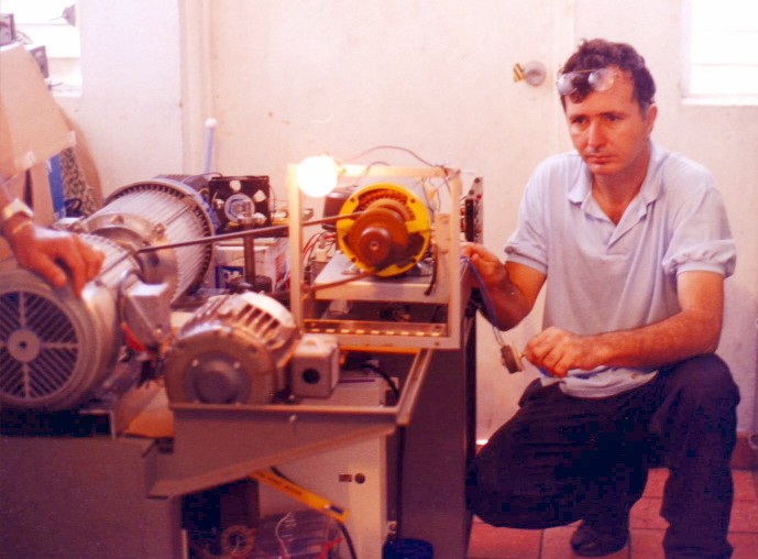
Next picture is first prototype used to test a 3PH generator–rotoconverter combo,
Power input: 240 W to Prime mover (Being touched by unseen witness at left) .
Generator required 380W for excitation at 120VAC (being touched by my person).
PARAMETERS:
Motor: US motor 7.5HP 3PH 3465 RPM Dual winding 9 Lead WYE
230/460VAC 60 CPS .
Prime mover input : 120VAC 2A (240W)
Alternator 500W Lab-volt (experimental model)
50-450 CPS (Speed regulated) 3PH 120VAC
380W excitation (self excited from generator), DC 120VDC 3.1666667A (380W) (low ripple rectified)
+ 100W load
------------------
= 480W Total Load
- 240W Prime Mover Input
------------------
= 240W Extra energy Gain
= 200 % efficiency ?
Instrumentation: Keithley digital DVM (2) (Not visible in picture).
Note: Friction & thermal loss not calculated

Above schematic is a common 3PH dual winding 230/460V motor wired to 480V run at 120V as a ROTOPHASE converter in semi-resonant mode.
Unit in first photo was made with OFF the shelve components, 7.5 HP 3PH 3450RPM 230/460VAC dual winding totally enclosed motor (fan removed).
System requires starting and running capacitance, the perfect starting capacitance is the one that gives same plate current value as a normal motor wired to run at 460V, but powered from 120VAC source, running capacitance tuned to give the lowest Amperage reading at intended motor load .
(ALL capacitors are AC 370V OIL no electrolytic"), some motors are better than others, for generator use you must choose the proper generator and motor combination to obtain OU gain.
It requires quite a good choice of items and common sense, a few turns of wire or a run weld in stator can change drastically the results from motors.
Up to date best performance being obtained from US motors 7.5 HP, BALDOR 3.5 HP, GE 3HP totally enclosed, dual winding 230/460V.
Higher HP will require professional expertise in industrial electricity and power eng. (not recommended for amateur experimenter) anyone engaged in this experiments must be familiar with safety procedures and basic electric and mechanic knowledge, voltages and rotating machinery must be handled with great care.
SEE basic diagram and connection.
– Hector
Latest UPDATE BELOW 7-01-02Subject: RV Basic level 1 Full MODEL Disclosure (Public domain) Please post with comments
Above schematic is RV looped system:
A 12V car battery initiates the system, it provides power to a 12VDC - 120VAC 1200W AC modified sine-wave inverter (EFF % 94%). This powers the ROTOVERTER (rotary-converter) main prime mover motor a 7.5 HP 3PH 230/460VAC 3465 rpm US motor windings in WYE wired at 460VAC shown as L1,L2,L3 … Rotoverter Alternator is an identical motor but wired for 230VAC, linked face to face with a motor shaft coupling to prime mover . In alternator L1,L2,L3 are connected to 3 capacitors coupled to 3 transformers, an extra capacitor is placed in any A,B,C phase as to provide rotor squirrel cage with inductive rotating field .
A rotating magnetic field is created loaded by the battery resistance and the Inverter load, the system is tuned to resonance providing a standing wave were the current node input to the battery exceeds the LOAD demand of the inverter recharging the system. The System Energy is maintained by the energy of the rotating squirrel cage in regressive reverse induction, requiring energy only to regain a percentage of the energy loss component from the resonant system acting as negative resistor.
In testing, battery changes resistance as recharging occurs this provokes system to detune from resonant to non-resonant modes drifting from OU to non-OU transform modes tendency is to dry out battery as this are not designed to work in cross current vectors variations.
Solutions: Use separated alternating battery banks and increase inverter input operation voltage (design it for 120VDC input) eliminating the transformers.
System gain comes from stochastic resonance and ZPE as the magnetic latching occurs within the core-wire LCR components of the motor and its capacitor driven rotary 3PH fields, in resonance, the time-energy decay is the only energy you require to replenish at to maintain it.
A resonant high Q circuit tends to have a fixed decay, this being as rule of thumb .372 (37.2 %) per full wave oscillation.
A spiral is manifested as logarithmic gain of 1.618 within sine-wave gain curve occurs were voltage “Electrons” are accelerated within virtual oscillatory wall (stochastic resonance).
Condensed original comments:
Battery provides primary power for 12VDC to 120VAC as to un prime mover (rotary-converter), second motor acts as an squirrel cage self-exited generator, a triple flux-capacitor LC tank tuned to best standing wave condition as to create standing wave current node internally in battery at 0 voltage to battery "negative resistor" At 0 volts "voltage" a negative current is created as to maintain a reverse flow (charge) to battery exceeding the forward drain of the inverter demand, detuning system with a forward charge at 10 amperes with a voltage rise of approximately .83333 V over the battery voltage charge produces OU transform from the 0 point standing wave component. System gains energy from stochastic resonance within the LC tank components draining energy from "thermal" signature of the ZPE and K thermodynamic-thermoelectric ambient heat (electron spin). This is a full disclosure of an operational and tested device, system is made of standard off shelve items, tuning is made by changing capacitor values and the proper selection of standard items for its construction, 3PH motors, 10:1 12V or 5:1 24V transformers with the proper core and winding values (standard) off shelve, diode bridges capacitor (all standard). It requires extreme knowledge in RF systems and electromagnetic resonance engineering.
Warning!: Do not operate above 10KW, or over extended time periods.
END....
Hector D Perez Torres
(Designer of the "RV" Rotoverter and "TV" transverter OU "transformation" devices)
Дата публикации: Прочитано: 55348 раз